
- Forum
- Geiger counter discussions
- Commericial geiger counters
- A little gem - The Yaorea YRG01 (Review & Mod)
A little gem - The Yaorea YRG01 (Review & Mod)
3 months 2 weeks ago #7500
by Simomax
Replied by Simomax on topic A little gem - The Yaorea YRG01 (Review & Mod)
Ugh, Ignore all of that.... The amp IC is powered all the time, whether on or off in the menu. Powered with USB I'm getting ~4.15v on pin 6 of the IC (VDD). I'll look some more and see if I find anything. It's hard to diagnose a faulty unit whne I only have a working one to play with.

Please Log in or Create an account to join the conversation.
3 months 2 weeks ago #7501
by Simomax
Replied by Simomax on topic A little gem - The Yaorea YRG01 (Review & Mod)
I have done a bit more digging but struggling to really work out how this amp IC works. What I have found is that the VDD (pin 6) is always powered with around 4.15v. This is smoothed by a couple of capacitors to the right of the IC. Pins 2 and 3 are connected together and go to one side of C44. The other connection on C44 is ground. Where Pins 2 and 3 connect to is not apparent. Looking at the datasheet it seems these go nowhere, except for that capacitor. When the clicker is turned on I get +2V on pins 2 and 3, and 0V when it is turned off. It seems something is enabling the IC, somewhere. Looking at the example in the datasheet it looks like pin 1 is enable. This is connected to the top pin on the little transistor/mosfet to the right of the amp IC. It is most likely that MOSFET that is turning the amp IC on and off. The other two pins on the MOSFET are ground and a pin on the MCU, likely a GPIO.
The audio input is on pin 4 of the amp IC. This is connected to R46 then C45, then goes to L12 at the left of the ribbon connection then to pin 3 of the ribbon cable. I'm numbering the from the left where PZ is printed on the board next to the ribbon connection. So working backwards the clicks audio comes over from pin 3 of the ribbon, into L12, then C45, then R46, then pin 4 of the IC.
You should expect to see ~4v on pin 6. Ground on pin 7. Pins 2 and 3 get ~2V when the clicks are turned on in the menu. Pin 1 is enable/disable and should get a high or low signal when the clicks are turned on and off. I don't know which way that is.
First things to check is do you have ~4V on pin 6. If so then do you have ~2V on pins 2 and 3 when the clicks are turned on. If all good then trace the audio path back over to the HV PSU board. If your ribbon cable soldering is anything like one of mine then it is suspect IMHO. Also, when you enable the clicks in the menu, do you hear any noise out of the speaker, as in noisy PSU type noise? If you are getting that when the clicks are on, then it is likely being powered.
The reason I have looked so much at this, is the amp IC should be almost impossible to blow up at the low voltages it is running at. The ~4V supply goes through a 2.2 ohm resistor that would take a little current off is something like the speaker outputs shorted. I find it hard to believe the IC is dead.
To look into this more I would need more time, like half a day or something and get the board under the microscope so I can trace it all out properly. Where are you? Not in the UK by any chance?
The following user(s) said Thank You: Quasar
Please Log in or Create an account to join the conversation.

3 months 2 weeks ago #7502
by Quasar
Replied by Quasar on topic A little gem - The Yaorea YRG01 (Review & Mod)
Thats interesting
On pin 6 i have only 0.08 volts for some reason
No sound on the speaker, no voltage either
Idk, maybe they just didn't test it and the amp was broken from the beginning, but on legs 1-4 i have some voltage, which supposedly should make the clicks, absolutely zero on the output though
And no, im in Russia, sadly..
In my city finding anything radioactive enough is pretty hard, so i have only 10 lil beads of uranium glass, which give around 70microR/h
Please Log in or Create an account to join the conversation.
3 months 2 weeks ago - 3 months 2 weeks ago #7504
by Bert490
Replied by Bert490 on topic A little gem - The Yaorea YRG01 (Review & Mod)
By the sounds of it, the power to the audio amp pin 6 is broken; if it's not ~4 v, the amp will never work. The power apparently comes through the ribbon cable from the HV PSU, the High Voltage Power Supply Unit (board). Look for a broken or badly soldered wire at either end of the ribbon cable. Simomax may remember which wire carries the 4 V.
Last edit: 3 months 2 weeks ago by Bert490.
Please Log in or Create an account to join the conversation.
3 months 1 week ago - 3 months 1 week ago #7505
by Simomax
Replied by Simomax on topic A little gem - The Yaorea YRG01 (Review & Mod)
I am working away at the moment and no lab here, nor any Geiger counters, so will have to do with what is in my head.
First of all, I just want to make sure that you are looking at the correct IC. The IC is U7, just above the speaker connections. I have roughly labelled a picture from memory. Pin 7 is ground and is also connected to the two surface mount capacitors to the right of the IC. Pin 6 is connected to the positive side of the capacitors and also one end of R45. The ~4v feed comes from the extreme right connection on the ribbon if memory serves me correct. It then goes to the right side of R45 (2.2 ohm IIRC) and then to the audio IC on pin 6. The two capacitors above R45 are for decoupling/smoothing on the +V for the audio IC. The ~4V on the right side of R45 also goes over to the right of the board where the components are around the LCD. If you were missing the ~4v feed coming over the ribbon I assume it would affect the LCD or the LED backlight for the LCD.
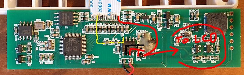
On the above image the red connections are the ~4V. Black is ground and the yellow one is the click signal coming from the HV PSU board. Doubly check you have the ~4V on that pin of the ribbon and to the right side of R45. When I'm back home in a week or so I can check further and find where that ~4V goes over near the LCD. Also check R45 and make sure you are getting around 2.2 ohms and it isn't open circuit. Also might be worth checking pins 2 & 3 and see if you are getting around 2V that I was getting when the clicks were enabled in the menu.
Another thing is make sure you are using a proper ground for the low voltage components. Don't use ground from the tube or ground from the battery/USB input as these may not give you the same ground as is used by the audio IC. Definitely don't use the tube ground as that is not connected to any ground the logic/LV stuff uses and the battery/USB ground may be switched via a MOSFET or some kind of IC for various reasons, such as turning IC's on and off.
On a side note - I was wondering what the wax was for. I have seen this used on sensitive circuits to keep moisture/humidity away in case it may change the behaviour of the circuit. I wondered why on a dumb audio IC/circuit. As it happens the wax is to hold a bodge wire in place. If you scrape it away, carefully, there is a small wire connecting a couple of components together. I suspect it was a missed trace when they designed the board.
First of all, I just want to make sure that you are looking at the correct IC. The IC is U7, just above the speaker connections. I have roughly labelled a picture from memory. Pin 7 is ground and is also connected to the two surface mount capacitors to the right of the IC. Pin 6 is connected to the positive side of the capacitors and also one end of R45. The ~4v feed comes from the extreme right connection on the ribbon if memory serves me correct. It then goes to the right side of R45 (2.2 ohm IIRC) and then to the audio IC on pin 6. The two capacitors above R45 are for decoupling/smoothing on the +V for the audio IC. The ~4V on the right side of R45 also goes over to the right of the board where the components are around the LCD. If you were missing the ~4v feed coming over the ribbon I assume it would affect the LCD or the LED backlight for the LCD.
On the above image the red connections are the ~4V. Black is ground and the yellow one is the click signal coming from the HV PSU board. Doubly check you have the ~4V on that pin of the ribbon and to the right side of R45. When I'm back home in a week or so I can check further and find where that ~4V goes over near the LCD. Also check R45 and make sure you are getting around 2.2 ohms and it isn't open circuit. Also might be worth checking pins 2 & 3 and see if you are getting around 2V that I was getting when the clicks were enabled in the menu.
Another thing is make sure you are using a proper ground for the low voltage components. Don't use ground from the tube or ground from the battery/USB input as these may not give you the same ground as is used by the audio IC. Definitely don't use the tube ground as that is not connected to any ground the logic/LV stuff uses and the battery/USB ground may be switched via a MOSFET or some kind of IC for various reasons, such as turning IC's on and off.
On a side note - I was wondering what the wax was for. I have seen this used on sensitive circuits to keep moisture/humidity away in case it may change the behaviour of the circuit. I wondered why on a dumb audio IC/circuit. As it happens the wax is to hold a bodge wire in place. If you scrape it away, carefully, there is a small wire connecting a couple of components together. I suspect it was a missed trace when they designed the board.
Attachments:
Last edit: 3 months 1 week ago by Simomax.
Please Log in or Create an account to join the conversation.
3 months 1 week ago #7506
by Quasar
Replied by Quasar on topic A little gem - The Yaorea YRG01 (Review & Mod)
First of all: Why is there a time when you don't have your counter with you =)
And, measuring the ribbon, instead of 4 volts im getting nothing on both sides of it...
And, measuring the ribbon, instead of 4 volts im getting nothing on both sides of it...
Please Log in or Create an account to join the conversation.
Moderators: Gamma-Man
- Forum
- Geiger counter discussions
- Commericial geiger counters
- A little gem - The Yaorea YRG01 (Review & Mod)
Time to create page: 0.280 seconds